Non Radio
The photograph to the right shows 3 PCBs. The left hand PCB contains the OCXO at the top then the DDS chip and below the LPF. The PCB with the heat sink is the PSU PCB and the one below is the PIC board that controls the DDS chip.
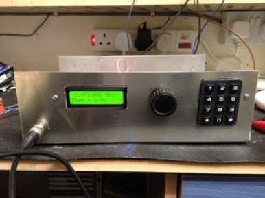
The front panel shows an LCD display, selector switch and keypad.
Welcome
To the web page of Mark, M0DFF
Locator JO02PW Last updated 19th June 2025
Copyright © M0DFF 2025
The Digital Signal Generator